Gateway and Mast
The carbon fiber pole raises a gateway, access point or beacon above the P-EDC. We recommend mounting and connecting the gateway before you power on, but either order works. Skip this page if you connect the P-EDC to a site network by cable.
Watch the video: Mounting the access point
What you need
| Part | Where it is |
|---|---|
| Main pole (4 sections) | Top drawer |
| Extension pole (optional, for more height) | Lid 1 |
| T-bar bracket | Top drawer |
| Beacon | Top drawer |
| Mako mount clip and PoE splitter | Accessory pouch (Mako 5600 kits) |
| Cellular gateway, pole mount and antennas | Top drawer (HiveRadar cellular gateway kits) |
Pole lengths
| Collapsed | Extended | |
|---|---|---|
| Main pole | 40 cm (1.3 ft) | 121 cm (3.9 ft) |
| Extension pole | 40 cm (1.3 ft) | 63 cm (2 ft) |
| Both | 80 cm (2.6 ft) | 184 cm (6 ft), 6.7 ft with the T-bar |
With the legs, pole, T-bar and beacon, the top sits up to 8.4 ft above the ground. Keep the load on top under 3 lb (1.36 kg) and centered.
1. Mount the device on the T-bar
The T-bar has a rail on one side for a gateway or AP, and a screw mount on the other for the beacon.
Only loosen the T-bar orientation knob slightly. Unscrewed fully, it falls off and is easily lost.
- Mako 5600
- HiveRadar cellular gateway
- Other AP or gateway
- Slide the mount clip from the accessory pouch into the back of the Mako.
- Slide the clip onto the T-bar rail and check it is secure.
- Fit the antennas, matching the number on each antenna to the port on the Mako.
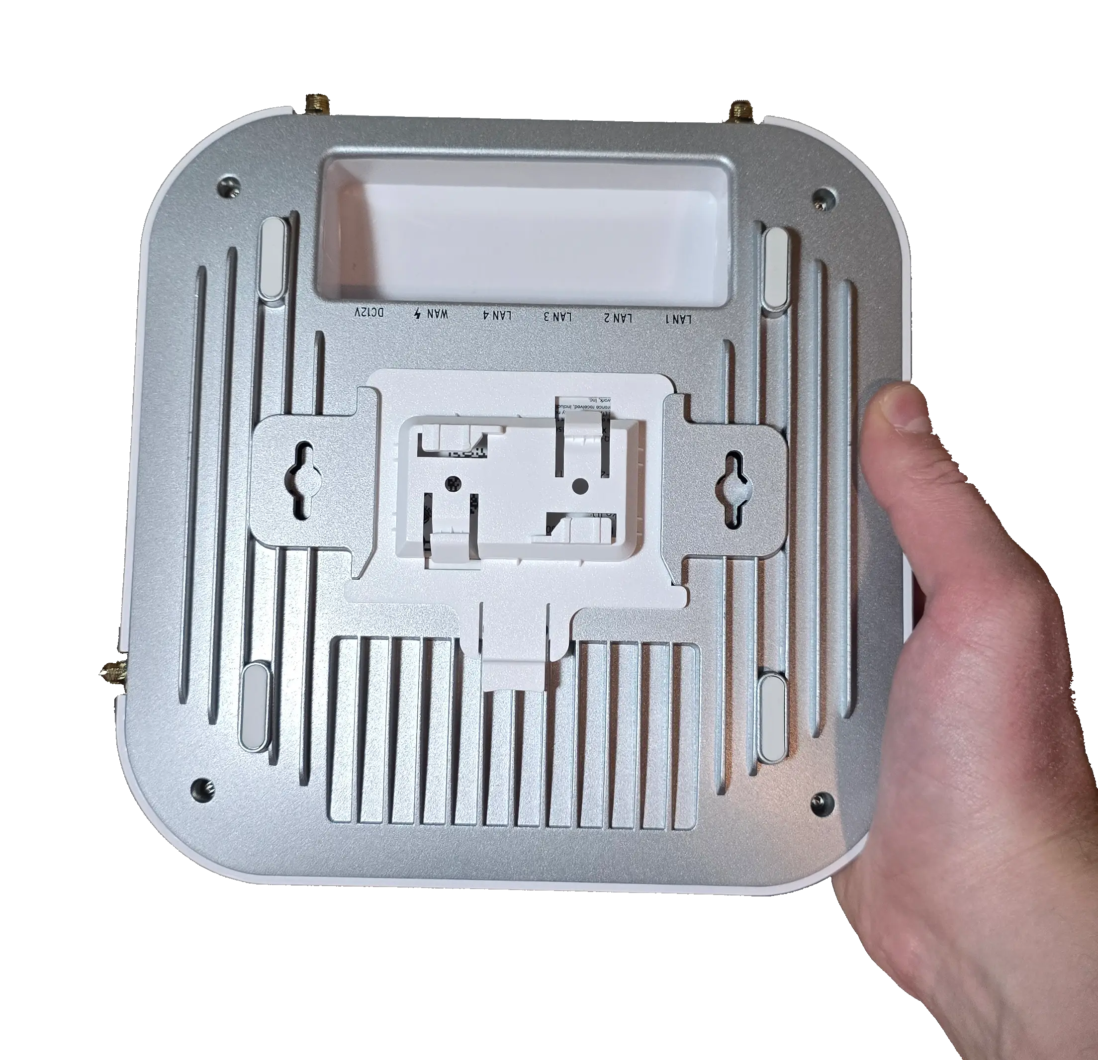
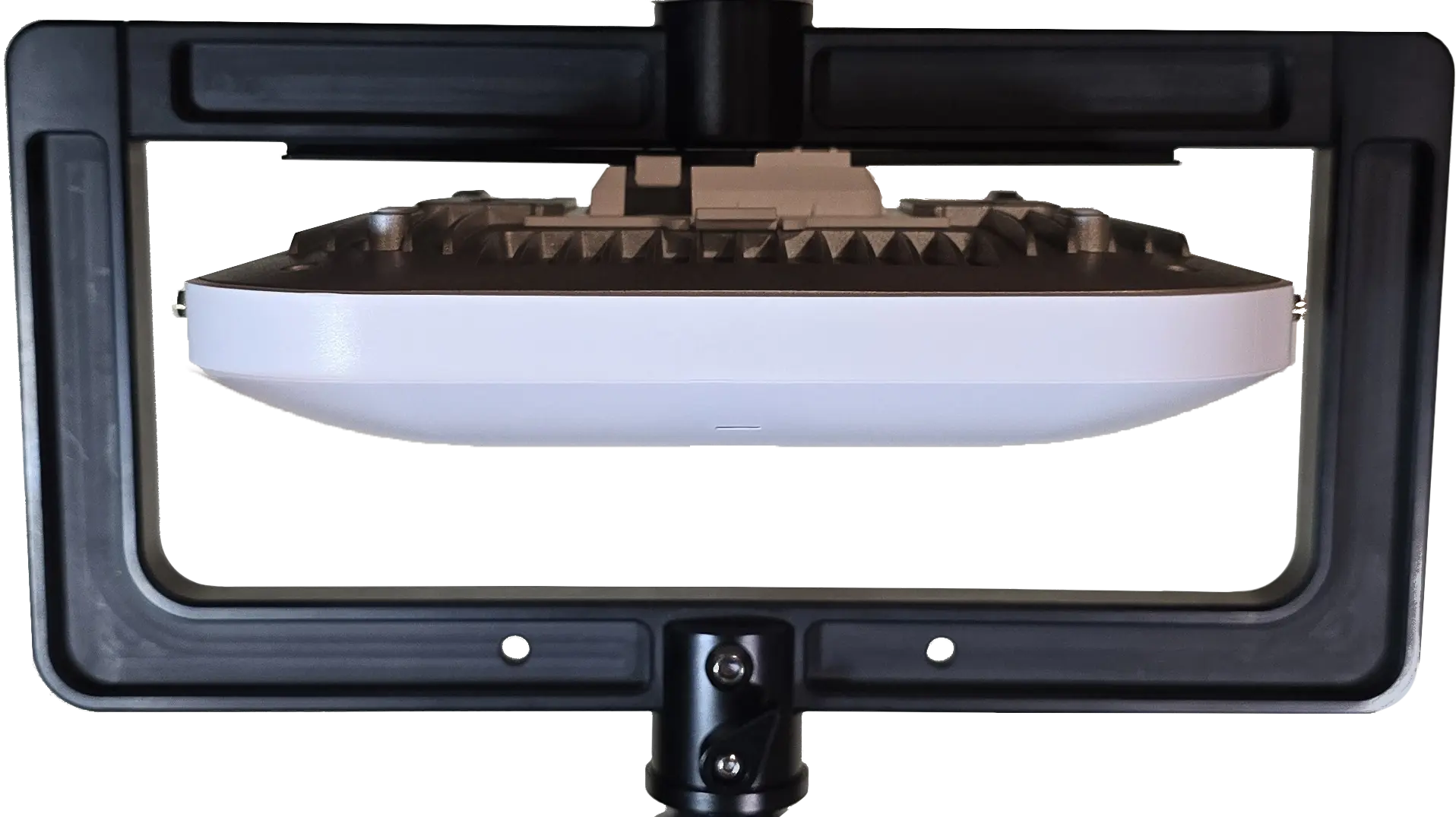
The cellular gateway doesn't use the T-bar.
- Take the gateway, its pole mount and its antennas out of the top drawer. The gateway comes with its LAN and WAN cables already threaded and labelled.
- To insert or change the SIM card, open the gateway with the tool from the accessory pouch.
- Screw the antennas onto the gateway.
- Screw the pole mount into the back of the gateway.
- Clip the pole mount around the top (thinnest) section of the pole.
For cabling and setup, see the CWG documentation.
Attach the device to the T-bar with its own bracket, following its manufacturer's instructions. HiveRadar can supply T-bar or pole-clamp adaptors for third-party devices; ask your partner.

Beacon (optional): screw it onto the T-bar's screw mount, or straight onto the top of the main pole if there is no T-bar. Press the button on its side to switch the light on and cycle the blinking.
2. Fit the T-bar to the pole
- Screw the T-bar clockwise onto the top of the main pole, not fully tight.
- Loosen the orientation knob slightly, turn the T-bar to face the right way, and tighten the knob.
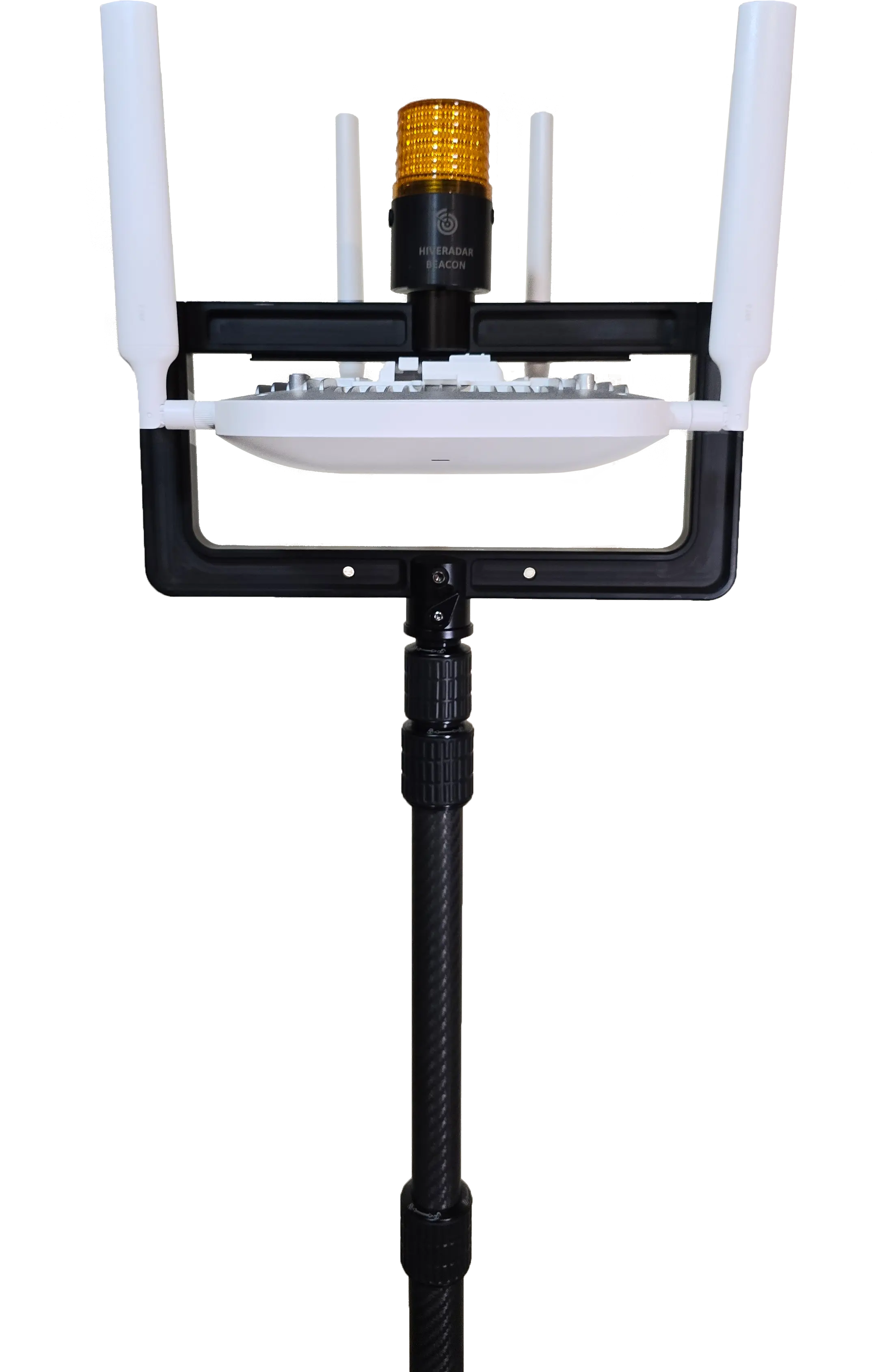
3. Mount the pole
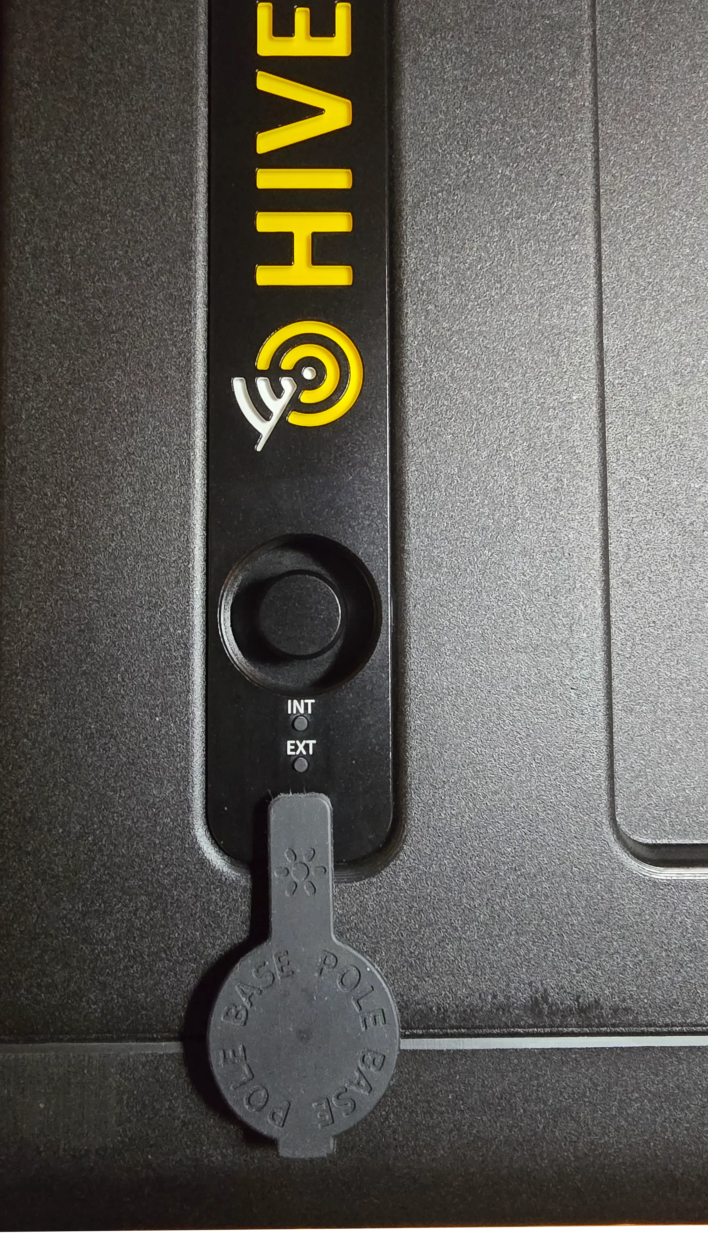
- Remove the rubber cover from the pole mount on top of the P-EDC. Keep it.
- If you use the extension pole, screw it clockwise into the mount first.
- If you use the main pole alone, extend its bottom section first, then screw it clockwise into the mount (or onto the extension pole).
- Check it is firm.
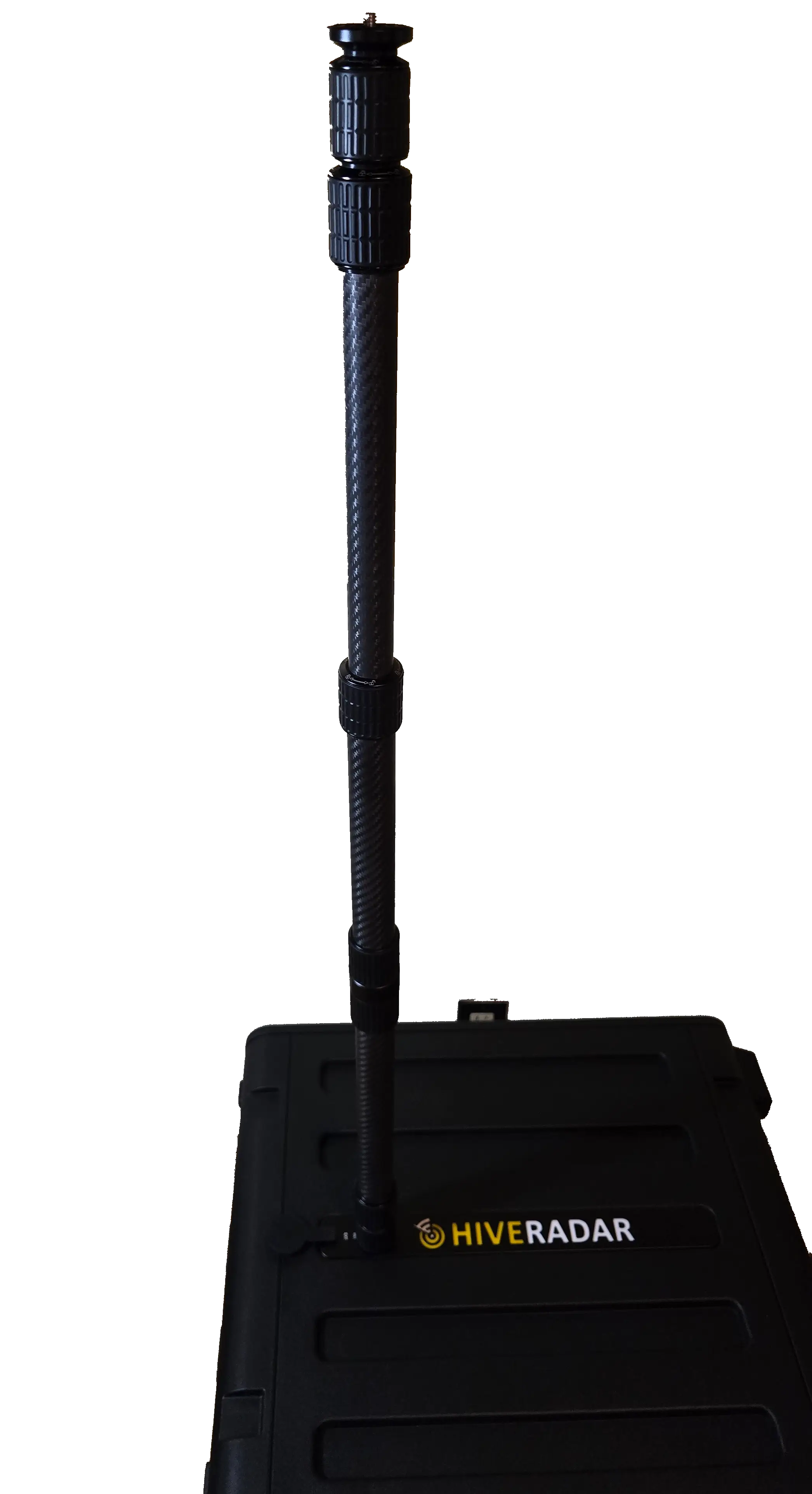
4. Extend the pole
Twist a joint counter-clockwise to unlock, pull the section up, then twist clockwise to lock. The lock symbols are printed on the pole. Lock every section before you let go.
There is no wind rating. Don't raise the mast in wind, and use guy wires only if you can't avoid it.
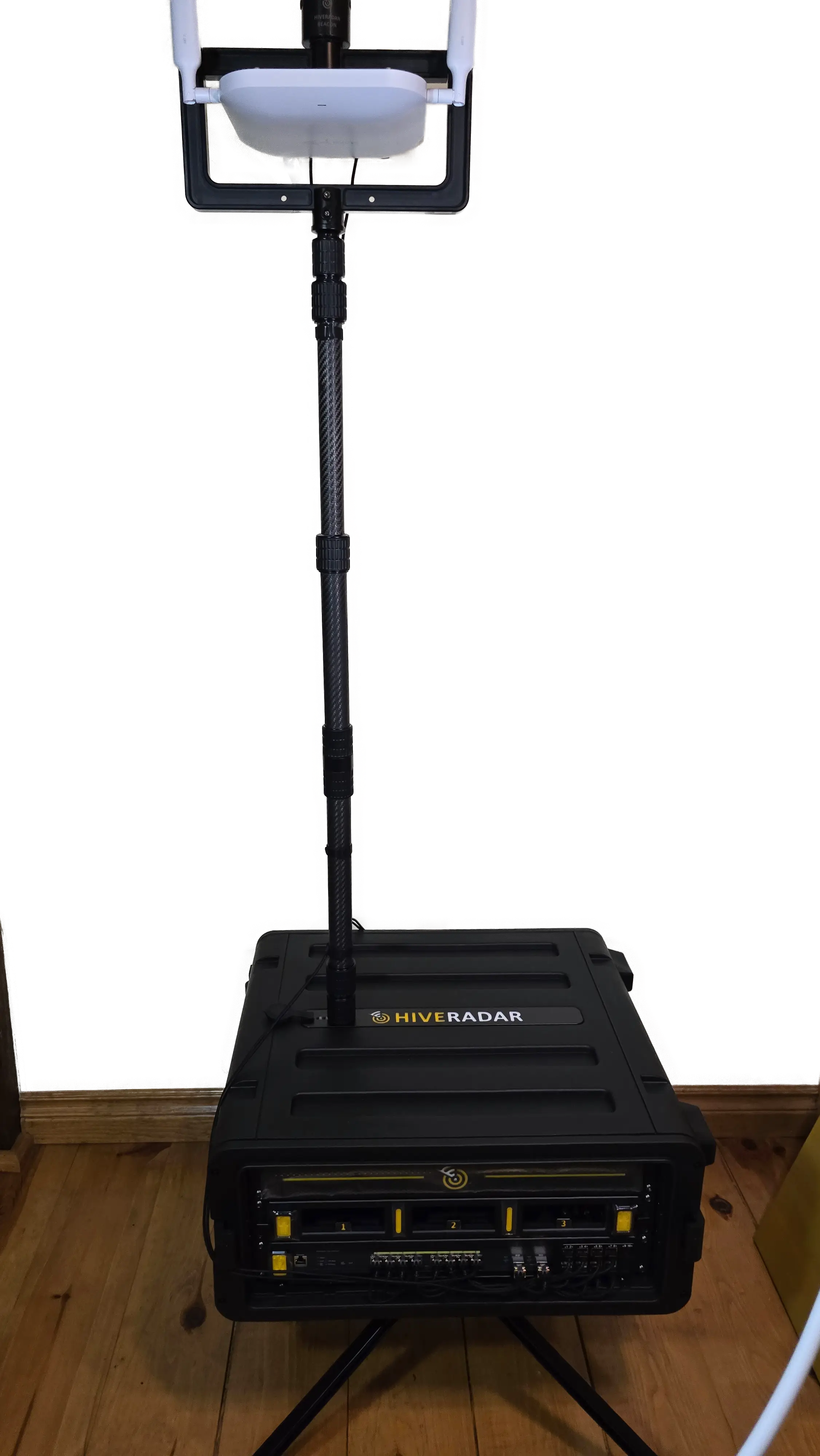
5. Connect the cables
- Mako 5600
- HiveRadar cellular gateway
- Other AP or gateway
The Mako is powered through the PoE splitter, so one cable runs to the switch.
- Ethernet cable from switch port 8 to the splitter's PoE input.
- Splitter data output to LAN 1 on the Mako.
- Splitter DC output to the DC port on the Mako.
- Run the cables down the pole with velcro straps, leaving a little slack at the top.
Fallback without the splitter
Use this only if the splitter is missing or faulty. The Mako can be powered over its WAN port with two cables: WAN to switch port 8 (power) and LAN to a second switch port (data). Data on port 8 then has to be isolated on the switch, so contact your partner first.
See the CWG documentation.
Connect the device to switch port 8. All RJ45 switch ports supply PoE by default; check your device's power needs.
If something doesn't fit
- Pole won't screw in: remove the rubber cover fully, and extend the main pole's bottom section first.
- T-bar won't hold its angle: tighten the orientation knob.
- Gateway has no power: check the chain: port 8 to splitter input, splitter data to Mako LAN 1, splitter DC to Mako DC. Check the switch is on.
Next: Power On